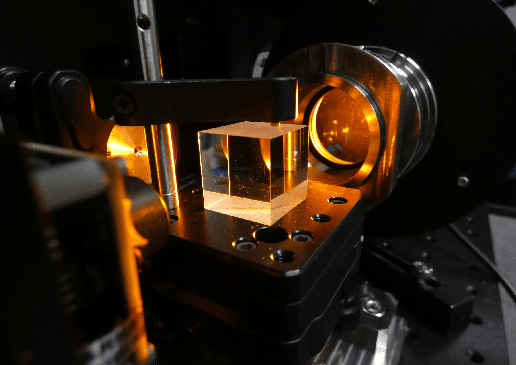
A magnificent invention from the late 80s, the Digital Micromirror Device is based on an assembly of individually-controlled micromirrors that reflect light onto a projection or light trap.
The combination of these high-frequency luminous fluxes creates a global image, which the human eye can interpret, or which can be used in specific optical equipment. Focus on a highly interesting optical tool with multiple applications.
How does the Digital Micromirror Device work?
The Digital Micromirror Device (DMD) was invented in 1987 by the American company Texas Instruments (TI). It is used in video projection systems to replace LCD projection technologies. The Digital Micromirror Device is based on the assembly of numerous microscopic mirrors into a common matrix. Depending on their position, these micromirrors either reflect or do not reflect the light they receive, each representing 1 pixel. Assembled on a common matrix, the Digital Micromirror Device can achieve, depending on the model, different levels of projection resolution: 640 x 360, 1920 x 1080, or higher.
"Depending on their position, these micromirrors reflect or not the light they receive, and each represents 1 pixel".
Each DMD micromirror can be rotated on one of its diagonal axes by an electrostatic attraction force. Depending on the force applied, it then occupies an active 'On' or inactive 'Off' state. In the 'On' position, the micromirror reflects light in the direction of image projection. Conversely, in the 'Off' position, it reflects light in the direction of a light trap to be absorbed.
The use and implementation of a Digital Micromirror Device requires a high level of expertise, depending in particular on the application in which it is deployed. Digital Micromirror Devices can be found in healthcare, the environment, industry and materials analysis. They are often custom-designed for integration into optical systems.
Two types of Digital Micromirror Device
Under the effect of the electrostatic attraction to which they are subjected, the Digital Micromirror Device's micromirrors toggle between the 'On' and 'Off' states. There are two types of DMD, depending on how the micromirrors are switched. The older Digital Micromirror Device uses a single axis of rotation that follows a single diagonal of each micromirror. The new DLP TRP (Tilt & Roll Pixel) model, on the other hand, uses both diagonals of each micromirror as its axis of rotation.
The Digital Micromirror Device with single-axis rotation

In the single-axis DMD, each micromirror is individually and digitally controlled, and can oscillate around its diagonal (see figure 1).

In this type of Digital Micromirror Device, each micromirror can be in one of three states: 'Off', 'On' or in a non-active state, which corresponds to its resting position. In this state, it receives no signal.
The DMD control signal is based on a matrix of 1s and 0s, or a black-and-white image whose size corresponds to the number of micromirrors.
Each point on the matrix, or each pixel on the image, controls the position of the micromirror as follows:
- If the pixel is white or the signal value is 1, the micromirror switches to the 'On' state and reflects the light received back to the projection lens.
- If the pixel is white or the signal value is 0, the micromirror switches to the 'Off' state and reflects the received light back to the light trap.

By combining the positions of the Digital Micromirror Device's micromirrors, an image can be projected through the projection lens onto a screen, a sample or a specific surface, depending on the application.
"The micromirror can switch from one state to another 100,000 times a second."
The special feature of the Digital Micromirror Device is that the micromirrors can switch from one state to another (from 'On' to 'Off' or from 'Off' to 'On') at very high frequency. The standard switching time is just 10 μs, or a frequency of 100KHz. In other words, the micromirror can switch from one state to the other 100,000 times per second.
As these image changes are far too rapid for the human eye, this allows white, black and other colors to alternate successively in the colors projected by the Digital Micromirror Device.
In the end, the eye only perceives an "averaging" of this visual combination, allowing it to see an image (or video) where monochrome, high-frequency images are actually projected.
The Digital Micromirror Device with two axes of rotation DLP TRP
Digital Micromirror Devices with two axes of rotation, found on the market today, work in the same way as those with single rotation, the only difference being that the micromirrors can oscillate on both diagonal axes (instead of one previously). This means (see figure 4) that the beams of the two-axis DMD for the 'On', 'Off' and 'Not active' states are no longer in the same plane.
Below: comparison of DMDs using 1 axis of rotation with DMDs using 2 axes of rotation :
- in blue, the non-active state,
- green 'On' status,
- red 'Off' status


The two axes of rotation of the Digital Micromirror Device's two-axis micromirrors follow the two diagonals. They are therefore perpendicular to each other. When the DMD is switched on, the micromirrors perform a first rotation on the first rotation axis (see figure 5).
They then position themselves in an intermediate active state. Depending on the information received, each micromirror then performs its second rotation towards an active 'On' or 'Off' state. This rotation is printed on the second diagonal axis, as shown in figure 6.


Optical systems used with Digital Micromirror Devices
To perform their function, Digital Micromirror Devices are generally coupled with other components: optical systems adapted to the application, an illumination system to bring light onto the DMD, and an optical system for image projection.
Furthermore, the use of mirrors within the DMD means that the source of the light signal and the reflected signal are on the same side (see figure 2). To separate these two light streams and avoid the risk of interference, so-called telecentric systems can be used. In this type of system, the entrance or exit pupil is located at infinity.

As shown in Fig. 7, the telecentric system ensures the same angular distribution. This means that the main rays of all fields and the rays passing through the center of the pupil are parallel to the system's output.
As a result, image points are illuminated at the same angle in the center and on the sides.
Using a telecentric optical system with a Digital Micromirror Device
When designing equipment comprising a DMD and a telecentric optical system, Arlumen's experts use a prism to separate the projection optical path from the illumination path, taking advantage of Total Internal Reflectance (TIR). By working on the critical angle of the prism's total internal reflection, it is possible to separate the illumination and projection optical paths, as shown in the Zemax simulation in figure 8.
The use of a DMD involves two optical components: illumination and projection. To illuminate the Digital Micromirror Device, the telecentric architecture distributes the light to all the DMD's micromirrors in exactly the same way. This is known as telecentric image illumination.

"The telecentric architecture will enable light to be distributed in exactly the same way to all the micromirrors".
The projection part is used to image the pattern on the DMD onto a projection plane. To achieve this, the projection system's entrance pupil must coincide with the illumination exit pupil. The projection system is thus telecentric-object.
In the example shown in figure 8, the total internal reflection of the prism is produced on the illumination path. We can also find examples with a total internal reflection of the prism on the projection path, called "Reverse TIR" or "RTIR Design".
The separation of illumination and projection optical paths can also be achieved without the use of a prism or telecentric system. These are referred to as non-telecentric systems.
A wide range of applications
Optical calculator
Arlumen's teams have created an optical calculator whose high density of micromirrors (1 million), coupled with high transfer speed, means that a very large number of combinations can be generated. Arlumen's experts have contributed to the miniaturization of this system with fine-tuned optimizations:
- Calculation and characterization of DMD diffraction orders
- Optimization of illumination optics to homogenize illumination over the surface of the Digital Micromirror Device
- Miniaturization

Design of a sensor to detect and quantify microplastics in wastewater
The Arlumen team was asked to design a system incorporating a Digital Micromirror Device capable of detecting and quantifying microplastics (MP) as part of the MICROPLASTIC2 collaborative project. The originality of this system lies in the fact that it uses a single photodetector combined with structured illumination, via the DMD, to image the samples to be analyzed.
This technique, classically known as compressive sensing, can be used to produce infrared images, replacing costly cameras in this spectral range.
Arlumen developed this system in 3 stages: the source part, the projection part and the detection part. Arlumen's expertise has enabled :
- Design an illumination system for the Digital Micromirror Device to ensure uniform flux distribution across the micromirrors and optimize power efficiency.
- Optimize the Hadamard matrix projection system on the sample, limiting optical aberrations.
- Choose a photodiode and optical filters suited to the detection wavelengths of the different polymers making up microplastics.
- Develop the detection system.
Structured lighting design for a 3D imaging tool
Arlumen implemented a highly intense and efficient structured lighting system using a DMD for one of its customers. The expertise developed during the project was particularly useful in selecting the LED used for the light source.
Delivering a flux of just a few optical watts, it requires electrical and thermal management (White W ) at the limit of what the Digital Micromirror Device can thermally withstand.
Arlumen's experts also defined and optimized the optical architecture of this equipment (RTIR ©TI) to carry the illumination beam (source / DMD / sample) thanks to a series of calculations and optical simulations in Zemax :
- Custom component sizing
- lenses
- doublets
- prisms
- microlens
- grating polarizers for very high optical fluxes
- Design of a mechano-optical architecture for the Digital Micromirror Device :
- thermal management (LEDs, optical elements and DMDs)
- stray-beam management to optimize 1000:1 lighting contrast
- respect optical constraints
- manufacture and qualify prototypes (5 units produced)